Machine Connectivity | 14 Juli 2020
How to Connect and Integrate a Modbus/TCP Server
Prerequisites
This lesson assumes that you want to integrate the Modbus/TCP protocol with the Cybus Connectware. To understand the basic concepts of the Connectware, please check out the Technical Overview lesson. To follow along with the example, you will also need a running instance of the Connectware. If you don’t have that, learn How to install the Connectware. Although we focus on Modbus/TCP here, we will ultimately access all data via MQTT. So you should also be familiar with MQTT. If in doubt, head over to our MQTT Basics lesson.
Introduction
This article will teach you the integration of Modbus/TCP servers. In more detail, the following topics are covered:
- Identifying Modbus datapoints
- Creating the Commissioning File
- Installing the Service via the Connectware Admin UI
- Verifying data in the Connectware Explorer
The Commissioning Files used in this lesson are made available in the Example Files Repository on GitHub.
Example Setup
For this example we presume that we have a device of the type Janitza UMG 604-EP PRO installed on our Ethernet network. This is a device for measuring and analyzing the electric power quality, which is equipped with a Modbus/TCP server.
Determining the datapoints
This device offers a lot of power analysis data you can access via Modbus, ranging over some thousands of address points. Although there is such a lot of interesting data, we assume that we just want to know the actual day of month, which is also provided and the real powers of L1-L3 as well as the utility frequency. Examining the Modbus address-list for UMG 604-PRO, we find the following addresses representing the date and time:
| Address | Format | Designation | Unit | Remarks                    |
|---------|--------|-------------|------|----------------------------|
| 0       | long64 | _REALTIME   | 2 ns | Time (UTC)                 |
| 4       | int    | _SYSTIME    | sec  | Time (UTC)                 |
| 6       | short  | _DAY        |      | Day (1 .. 31)              |
| 7       | short  | _MONTH      |      | Month (0=Jan, .. 11=Dec)   |
| 8       | short  | _YEAR       |      | Year                       |
| 9       | short  | _HOUR       | h    | Hour (1 .. 24)             |
| 10      | short  | _MIN        | min  | Minute (1 .. 59)           |
| 11      | short  | _SEC        | s    | Second (1 .. 59)           |
| 12      | short  | _WEEKDAY    |      | Weekday , (0=Sun .. 6=Sat) |Code-Sprache: YAML (yaml)
We also find the following addresses representing frequently required readings:
| Address | Format | Designation   | Unit | Remarks                               |
|---------|--------|---------------|------|---------------------------------------|
| 19000   | float  | _G_ULN[0]     | V    | Voltage L1-N                          |
| 19002   | float  | _G_ULN[1]     | V    | Voltage L2-N                          |
| 19004   | float  | _G_ULN[2]     | V    | Voltage L3-N                          |
| 19006   | float  | _G_ULL[0]     | V    | Voltage L1-L2                         |
| 19008   | float  | _G_ULL[1]     | V    | Voltage L2-L3                         |
| 19010   | float  | _G_ULL[2]     | V    | Voltage L3-L1                         |
| 19012   | float  | _G_ILN[0]     | A    | Apparent current, L1-N                |
| 19014   | float  | _G_ILN[1]     | A    | Apparent current, L2-N                |
| 19016   | float  | _G_ILN[2]     | A    | Apparent current, L3-N                |
| 19018   | float  | _G_I_SUM3     | A    | Vector sum; IN=I1+I2+I3               |
| 19020   | float  | _G_PLN[0]     | W    | Real power L1-N                       |
| 19022   | float  | _G_PLN[1]     | W    | Real power L2-N                       |
| 19024   | float  | _G_PLN[2]     | W    | Real power L3-N                       |
| 19026   | float  | _G_P_SUM3     | W    | Psum3=P1+P2+P3                        |
| 19028   | float  | _G_SLN[0]     | VA   | Apparent power L1-N                   |
| 19030   | float  | _G_SLN[1]     | VA   | Apparent power L2-N                   |
| 19032   | float  | _G_SLN[2]     | VA   | Apparent power L3-N                   |
| 19034   | float  | _G_S_SUM3     | VA   | Sum; Ssum3=S1+S2+S3                   |
| 19036   | float  | _G_QLN[0]     | var  | Reactive power L1 (fundamental comp.) |
| 19038   | float  | _G_QLN[1]     | var  | Reactive power L2 (fundamental comp.) |
| 19040   | float  | _G_QLN[2]     | var  | Reactive power L3 (fundamental comp.) |
| 19042   | float  | _G_Q_SUM3     | var  | Qsum3=Q1+Q2+Q3 (fundamental comp.)    |
| 19044   | float  | _G_COS_PHI[0] | -    | CosPhi; UL1 IL1 (fundamental comp.)   |
| 19046   | float  | _G_COS_PHI[1] | -    | CosPhi; UL2 IL2 (fundamental comp.)   |
| 19048   | float  | _G_COS_PHI[2] | -    | CosPhi; UL3 IL3 (fundamental comp.)   |
| 19050   | float  | _G_FREQ       | Hz   | Measured frequency                    |Code-Sprache: Bash (bash)
In the documentation there is also a table defining the size and range of the terms used in the column Format, which we will need for specifying our endpoints.
| Type   | Size   | Minimum  | Maximum  |
|--------|--------|----------|----------|
| char   | 8 bit  | 0        | 255      |
| byte   | 8 bit  | -128     | 127      |
| short  | 16 bit | -2^15    | 2^15-1   |
| int    | 32 bit | -2^31    | 2^31-1   |
| uint   | 32 bit | 0        | 2^32-1   |
| long64 | 64 bit | -2^63    | 2^63-1   |
| float  | 32 bit | IEEE 754 | IEEE 754 |
| double | 64 bit | IEEE 754 | IEEE 754 |Code-Sprache: YAML (yaml)
Writing the Commissioning File
The Commissioning File is a set of parameters which describes the resources that are necessary to collect and provide all the data for our application. It contains information about all connections, data endpoints and mappings and is read by Connectware. To understand the file’s anatomy in detail, please consult the Reference docs. To get started, open a text editor and create a new file, e.g. modbus-example-commissioning-file.yml. The Commissioning File is in the YAML format, perfectly readable for human and machine! We will now go through the process of defining the required sections for this example:
- Description
- Metadata
- Parameters
- Resources
Description and Metadata
These sections contain more general information about the commissioning file. You can give a short description and add a stack of metadata. Regarding the metadata, only the name is required while the rest is optional. We will just use the following set of information for this lesson:
description: >

  Modbus/TCP Example Commissioning File
  Cybus Learn - How to connect and integrate an Modbus/TCP server
  https://learn.cybus.io/lessons/XXX/

metadata:

  name: Modbus/TCP Example Commissioning File
  version: 1.0.0
  icon: https://www.cybus.io/wp-content/uploads/2019/03/Cybus-logo-Claim-lang.svg
  provider: cybus
  homepage: https://www.cybus.ioCode-Sprache: YAML (yaml)
Parameters
Parameters allow the user to customize Commissioning Files for multiple use cases by referring to them from within the Commissioning File. Each time a Commissioning File is applied or reconfigured in the Connectware, the user is asked to enter custom values for the parameters or to confirm the default values.
parameters:

  modbusHost:
    type: string
    description: Modbus/TCP Host
    default: 192.168.123.123

  modbusPort:
    type: integer
    default: 502Code-Sprache: YAML (yaml)
We are defining the host address details of our Modbus/TCP server as parameters, so they are used as default but can be customized in case we want to connect to a different server.
Resources
In the resources section we declare every resource that is needed for our application. The first resource we need is a connection to the Modbus/TCP server.
resources:

  modbusConnection:
    type: Cybus::Connection
    properties:
      protocol: Modbus
      connection:
        host: !ref modbusHost
        port: !ref modbusPortCode-Sprache: YAML (yaml)
After giving our resource a name – for the connection it is modbusConnection – we define the type of the resource and its type-specific properties. In case of Cybus::Connection we declare which protocol and connection parameters we want to use. For details about the different resource types and available protocols, please consult the Reference docs. For the definition of our connection we reference the earlier declared parameters modbusHost and modbusPort by using !ref.
The next resources needed are the data points that we have selected earlier. Let’s add those by extending our list of resources with some endpoints.
  dayOfMonth:
    type: Cybus::Endpoint
    properties:
      protocol: Modbus
      connection: !ref modbusConnection
      subscribe:
        fc: 3
        length: 1
        interval: 2000
        address: 6
        dataType: int16BE

  realPowerL1:
    type: Cybus::Endpoint
    properties:
      protocol: Modbus
      connection: !ref modbusConnection
      subscribe:
        fc: 3
        length: 2
        interval: 2000
        address: 19020
        dataType: floatBE

  realPowerL2:
    type: Cybus::Endpoint
    properties:
      protocol: Modbus
      connection: !ref modbusConnection
      subscribe:
        fc: 3
        length: 2
        interval: 2000
        address: 19022
        dataType: floatBE

  realPowerL3:
    type: Cybus::Endpoint
    properties:
      protocol: Modbus
      connection: !ref modbusConnection
      subscribe:
        fc: 3
        length: 2
        interval: 2000
        address: 19024
        dataType: floatBE

  frequency:
    type: Cybus::Endpoint
    properties:
      protocol: Modbus
      connection: !ref modbusConnection
      subscribe:
        fc: 3
        length: 2
        interval: 2000
        address: 19050
        dataType: floatBECode-Sprache: YAML (yaml)
Each resource of the type Cybus::Endpoint needs a definition of the used protocol and on which connection it is rooted. Here you can easily refer to the previously declared connection by using its name. Furthermore we have to define which Modbus address the endpoint should read from or write to by giving the function code fc, the length , the interval, the address and the dataType.
Function code
The function code fc defines the operation of the request. To learn more about the different codes and their purpose, you can consult one of many sources on the web, e.g. Simply Modbus. However, the exact implementation of the function codes may vary from manufacturer to manufacturer and is in some sources described as „artistic freedom“ in designing their modbus devices. Which function code to use on which data is therefore also depending on your device and its structure of register addressing, so also check out the documentation of your device. For the device we utilize in this example, we can either use function code 3 or 4 to read the analogue values, so we just use 3.
Length
The length describes how many registers should be read starting at the specified address. The registers of a modbus device have a length of 16 bits. Assuming we want to read the value of day of month, which is given in the format „short“, we learn from the table defining the actual size of the formats, it has a size of 16 bits and therefore a length of one register, so we define the property length as 1. For the other endpoints we define the length as 2, since the format „float“ is 32 bits long, using two registers.
Interval
Optionally, we can define the poll interval in milliseconds, defining how frequently a value is requested from the server, which is 1000 ms by default. To reduce the bandwidth demand we set the interval of our endpoints to 2000 ms.
Address
We looked at the modbus address list of the device before and found the datapoints representing the day of month on address 6 and the readings of real power L1-L3 on addresses 19020,19022 and 19024 and the frequency on address 19050.
Data type
The property dataType is optional, but in fact you will get a buffer value in case you do not specify the data type explicitly, which at first you would have to parse yourself. To avoid this, we define the data types for the power values and frequency as floatBE, since from the address list we learned, those were in the format „float“ and the section „Byte sequence“ of this document gives us the information „The addresses described in this address list supply the data in the „Big-Endian“ format.“, which „BE“ stands for.
Looking at the endpoint „dayOfMonth“ we see, the format of its address is „short“, which corresponding to the table of formats matches the size and range of a 16-bit integer data type. Following this, we define the data type of the endpoint „dayOfMonth“ as int16BE. You can find all available data types for Modbus in the Reference docs.
MQTT Mapping
To this point we are already able to read values from the Modbus/TCP server and monitor them in the Connectware Explorer or on the default MQTT topics related to our service. To achieve a data flow that would satisfy the requirements of our integration purpose, we may need to add a mapping resource to publish the data on topics corresponding to our MQTT topic structure.
  mapping:
    type: Cybus::Mapping
    properties:
      mappings:
        - subscribe:
            endpoint: !ref dayOfMonth
          publish:
            topic: 'janitza/status/day'
        - subscribe:
            endpoint: !ref realPowerL1
          publish:
            topic: 'janitza/measurement/realpower/1'
        - subscribe:
            endpoint: !ref realPowerL2
          publish:
            topic: 'janitza/measurement/realpower/2'
        - subscribe:
            endpoint: !ref realPowerL3
          publish:
            topic: 'janitza/measurement/realpower/3'
        - subscribe:
            endpoint: !ref frequency
          publish:
            topic: 'janitza/measurement/frequency'Code-Sprache: YAML (yaml)
In this case the mapping defines which endpoints value is published on which MQTT topic. In case you want to perform a write operation to your device, you simply have to reverse the data flow and map it from the MQTT topic to the according endpoint like this:
  - subscribe:
      topic: 'janitza/control/setvalue'
    publish:
      endpoint: !ref valueToSetCode-Sprache: YAML (yaml)
Then you can write to the endpoint by simply publishing on this MQTT topic. Please note that write messages have to be in JSON format containing the value as follows:
{
  "value": true
}Code-Sprache: YAML (yaml)
This message has the obligatory key „value“, which can contain a value of any data type (which should match the concerning endpoint): For instance boolean values just use true/false, integers are represented by themselves like 3, decimals similarly appear as 10.45 and strings are written in "quotes".
Installing the Commissioning File
You now have the Commissioning File ready for installation. Head over to the Services tab in the Connectware Admin UI and hit the (+) button to select upload the Commissioning File. You will be asked to specify values for each member of the section parameters or confirm the default values. With a proper written Commissioning File, the confirmation of this dialog will result in the installation of a Service, which manages all the resources we just defined: The connection to the Modbus/TCP server, the endpoints collecting data from the server and the mapping controlling where we can access this data. After enabling this Service you are good to go on and see if everything works out!
Verifying the data
Now that we have a connection established between the Modbus/TCP server and Connectware, we can go to the Explorer view, where we see the tree structure of our newly created data points.
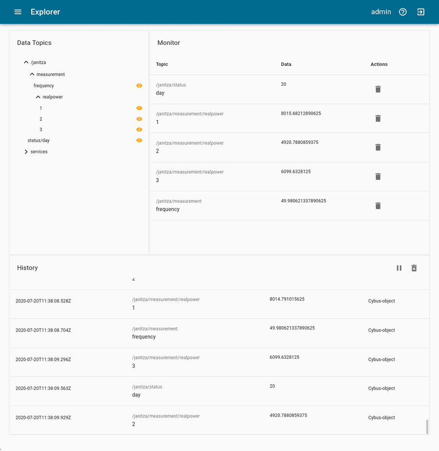
On MQTT topics the data is provided in JSON format containing a timestamp and a value key of which the value represents the data as received from the device:
{
  "value":"2020-07-14T11:43:06.632Z",
  "timestamp":1594726986632
}Code-Sprache: Bash (bash)
Summary
Summarizing this lesson, at first we learned how to identify addresses of the desired data points in the address list of our device along with definitions and conventions about their representation. Given that information, we created a Commissioning File and installed the Service on the Connectware. In the Explorer we finally saw the live data on corresponding MQTT topics and are now ready to go further with our Modbus integration.
Where to go from here
The Connectware offers powerful features to build and deploy applications for gathering, filtering, forwarding, monitoring, displaying, buffering, and all kinds of processing data… why not build a dashboard for instance? For guides check out more of Cybus Learn.
Check out our media to this article: